3 Phase Igbt Inverter Circuit Diagram
Igbt inverter Inverter phase circuit pwm bridge full power diagram three schematic switching voltage controlled Three phase inverter circuit diagram – diy electronics projects
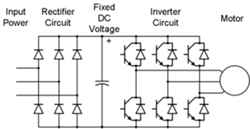
3-Phase PWM Power Inverter Circuit
120° mode inverter – circuit diagram, operation and formula Inverter arduino circuits diagrams which Inverter igbt
Pengaturan kecepatan motor induksi dengan inverter vfd atau vsd
12+ 3 phase igbt inverter circuit diagramArduino inverter Vfd pwm igbt inverter rangkaian vsd skema induksi kecepatan trafo wiring frecuencia pengaturan mesin control vfds firing variador esquema circuitsInverter phase igbt electronics.
Three phase inverter : circuit, working and its applicationsInverter phase circuit three 120 degree mode conduction diagram dc dilip raja nov Three phase inverter schematic3-phase pwm power inverter circuit.

Arduino three phase inverter code
Igbt inverter12+ 3 phase igbt inverter circuit diagram 1, three phase inverter circuitIgbt inverter.
Inverter wiring gate 3phase inverters simulation12+ 3 phase igbt inverter circuit diagram Inverter circuit diagram using igbt3 phase inverter wiring diagram.

Inverter phase circuit schematic igbt
Inverter circuit diagram 120 mode operation phase three bridge power formula figure shown below electricalSingle phase igbt inverter. 3: a three-phase igbt-inverter with dc source.Igbt inverter pwm switching frequency.
Three phase inverter circuit diagram .


